| Robotic Blimp Hardware (Ian
Mudie) Also see
http://gridswarms.essex.ac.uk
|
|
|
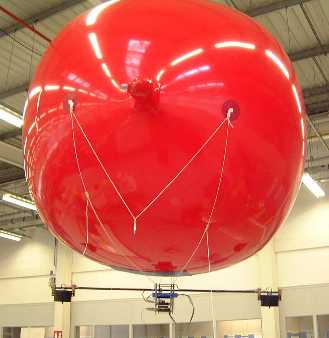
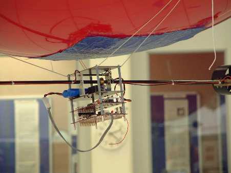
My research is based upon a helium filled flying balloon. To enable the balloon to be controlled, there is a gondola containing 2 vectored ducted fan units and controlling electronics. The electronics consists of 4 individual modules that are stacked on top of each other with PC-104 stacking connectors. Each module performs a specific function, these being Master Control with Radio Data Communication, Sonar Range finding, Infrared Localisation and Motor Control. Each module contains at least one PIC microcontroller and communication between modules is achieved with the I2C Communications Protocol. The Master Control module will eventually control the position of the blimp by firstly analysing data from the Sonar Rangefinder and Infrared Localisation Modules. From this data the required settings for the motors will be calculated and passed over the I2C communication channel to the Motor Control Module. The photos below illustrate this arrangement. Higher resolution images can be viewed by clicking on the pictures.
|
|
|
|
|
|
The Blimp Robot filled with Helium |
A Closeup picture of the Gondola |
| As mentioned above, the gondola is constructed from individual modules that are stacked on top of each other as required. Each of the four modules required the same stages of development. These were as follows:-
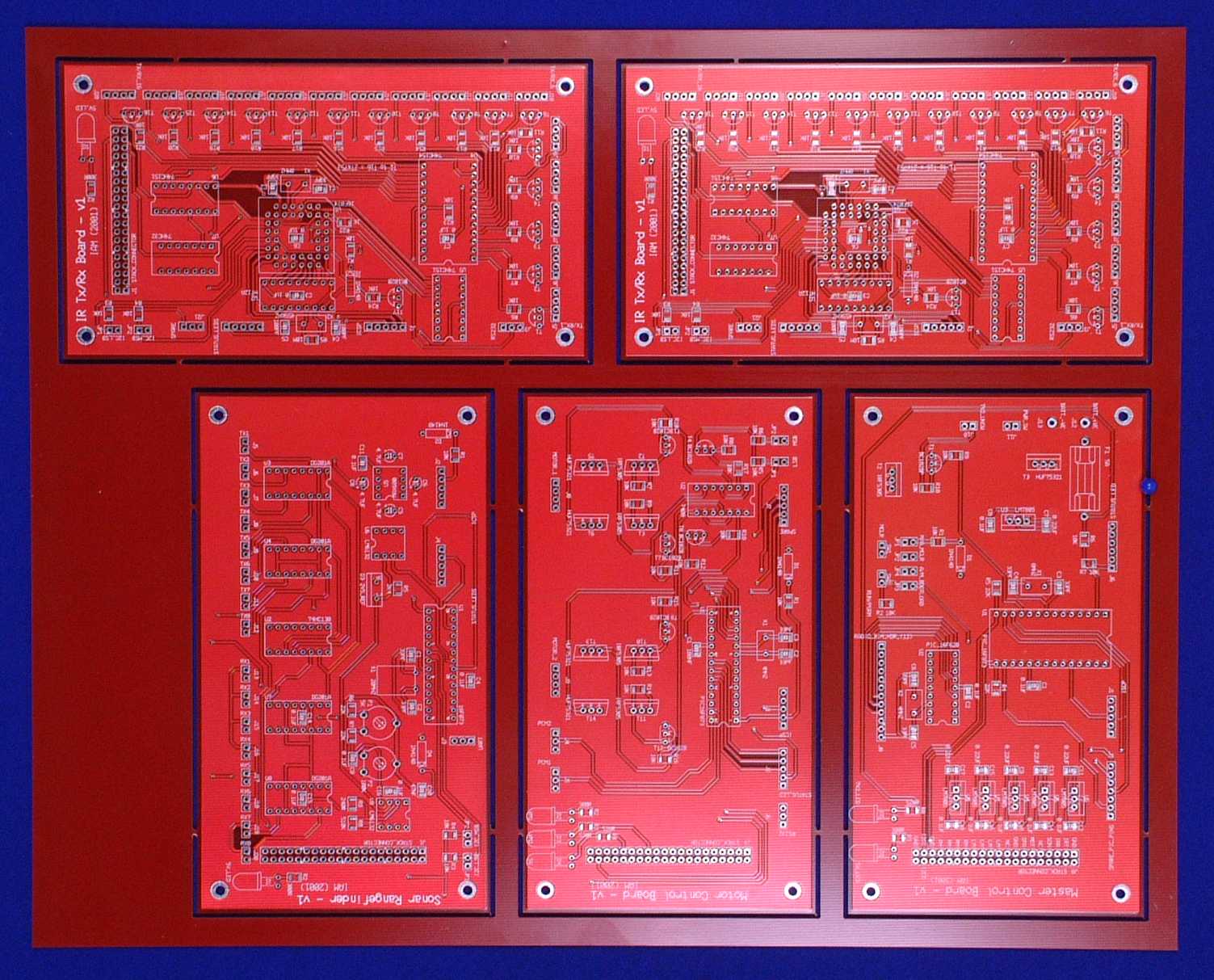
After repeating the above process four times, the next stage in the development of the robot was to manafacture the 4 different PCB's (Printed Circuit Boards). The first method tried was with a PCB routing machine. This produced a perfectly etched PCB but I had to manually "through hole plate" the PCB myself (THP is how the top and bottom tracks on a PCB connect). This method was found to be unsuitable for two reasons i.) It takes many hours to manually "through hole plate" each PCB, and ii.) The reliability of the manually THP board was not high enough. It was at this point that a collage of mine suggested that I have the PCB's made professionally. He suggested a company to use and I found the price to lower that what I had antisipated. They were able to produce 6 complete sets of PCB's (6 biscuits with 5 PCB's on each biscuit) for under £500. A biscuit as received from the manufactures is shown in the following photo.
|
|
|
A biscuit of PCB's direct from the manufacturer |
|
|
The next step of course is to populate the PCB's with ccomponets. These were obtainted from CPC, Farnell and RS (all of which take personal orders). After a few minor corrections to the PCB's all were fully working. A detailed discription of each module along with circuit diagrams and photos can be found by clicking on the relevent link below.
|