| Motor Control Module
|
|
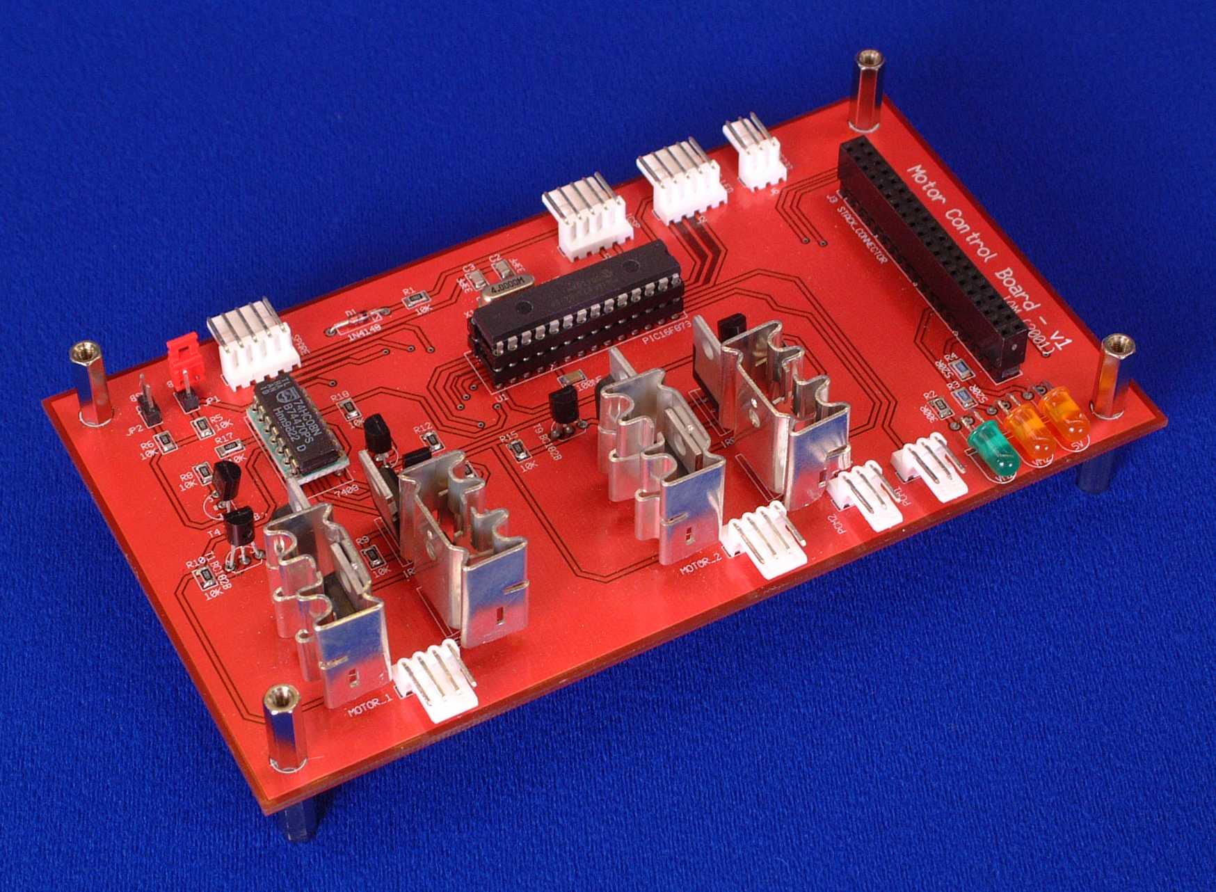
The Motor Control Module provides speed and position control for 2 Ducted Fan Units (DFUs), that enable the Blimp to manoeuvre. The Motor Control Module receives instructions regarding the direction and speed of the two fan units along with position data for up to 2 RC Servos from the Master Control Module. This data is transferred across the I2C Communications Bus. The photograph below is of a fully populated Motor Control Module.
|
|
A fully populated Motor Control Module
|
How it WorksA circuit diagram for the Motor Control Module in PDF format can be downloaded here, or a GIF version can be viewed here. All processing on this module is provided by U1, a PIC 16F873 microcontroller. The reasons for choosing this microcontroller are i) It has I2C Communication Capability, ii) It contains 2 PWM controllers, and iii) It has more than enough general purpose IO. The speed and direction of the DFUs is controlled by custom H-Bridges running off the PWM (Pulse Width Modulation) Ports on the microcontroller. PWM is a method of power control, where the length of time that power is supplied to a device varies with required output. For example, if I wished to run a light bulb at 10% brightness, I could turn the light on for 1ms and off for 9ms, hence I would be supplying the bulb with 1/10th of the power available. The ratio of supplying power to not supplying power is known as the duty cycle, e.g. a 50% duty cycle in our example would be on for 5ms and then off for 5ms. There are 2 connections from the microcontroller to each of the H-Bridges (called so due to it's shape when drawn in circuit diagram form). One connection provides the PWM signal (CCP1 and CCP2) and the other controls the direction. To stop the motors, a PWM signal with 0% duty cycle is output by the microcontroller.
When I constructed a prototype of the Motor Control Module on Bread Board, I had the correct motors and they were attached to the circuit. What I did not have was the DFU propellers, and so was testing the circuit without load on the motors. Once the PCB was constructed and attached to the DFUs, I found that my "Low Side" FETs were getting very hot (approx. 130 degrees) due to the current that the motor was drawing under load. Luckily, there was enough room on the PCB to add heatsinks to these components which reduced the temperature to a more comfortable 60 degrees. One thing I have learnt from this is to ensure my test scenario is as close as possible to the final application. If you have any questions about anything you see on these pages, then please e-mail me at i.mudie@uwe.ac.uk.
|
|