| Sonar Range-Finding Module
|
|
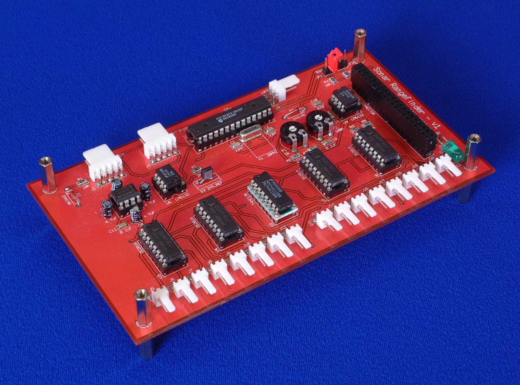
The Sonar Range-Finding Module is used for altitude information (height from floor and ceiling), collision avoidance (walls and other Blimps) and separation control (distance from neighbouring Blimps). Up to 8 sonar transmitter/reciver pairs can be attached to each module, with distance readings being held in memory until requested by the Master Control Module. The photograph below shows a fully populated Sonar PCB.
|
|
A fully populated Sonar Range-Finding Module
|
How it WorksThe details for a single channel version of a sonar range-finder can be found at http://www.mindspring.com/~sholmes/robotics/ultrasnd.htm and this forms the basis of the circuit described here. The above web pages are very detailed so I will not repeat the full working of the sonar system here, just the parts that I have added A circuit diagram for the Sonar Range-Finding Module in PDF format can be downloaded here, or a GIF version can be viewed here. The single channel circuit available form the above web site was converted into an 8 channel version by adding analogue multiplexors (DG201A) U3, U4, U7 and U8. These devices can either be supplied with a split (+ve and -ve) power rail for switching of bipolar signals or a single supply (e.g. 5v) and a connection to Gnd for digital applications. Both methods are used in this circuit as the transmitter multiplexors switch signals between +10v and -10v, while the receiver multiplexors only deal with signals between 5v and Gnd. The four multiplexors have a total of 16 control lines. As the ultrasonic Transmitter and Receiver pairs must always be selected together, the number of control lines can be reduced to 8 by connecting the control lines for TX Mux 1-8 and RX Mux 1-8 together. But the number of control lines can be reduced ever further by using U2 (74HC138), a 3:8 decoder. This is a simple digital device that takes a 3 bit binary input (000=1 to 111=8) and uses this to select which of 8 output lines should go low, and hence which of the 8 pairs of sonar sensors should be used. The final total of control lines is not actually 3 but is 4, as there is an enable input that sets all output lines to high (none of the multiplexors selected) when it is taken low. If you have any questions about anything you see on these pages, then please e-mail me at i.mudie@uwe.ac.uk.
|
|