 |
 |
|
The IR Localisation Module (As should have been)
|
The IR Localisation Module with (mistake) Adapter
|
Infrared Localisation Module |
|
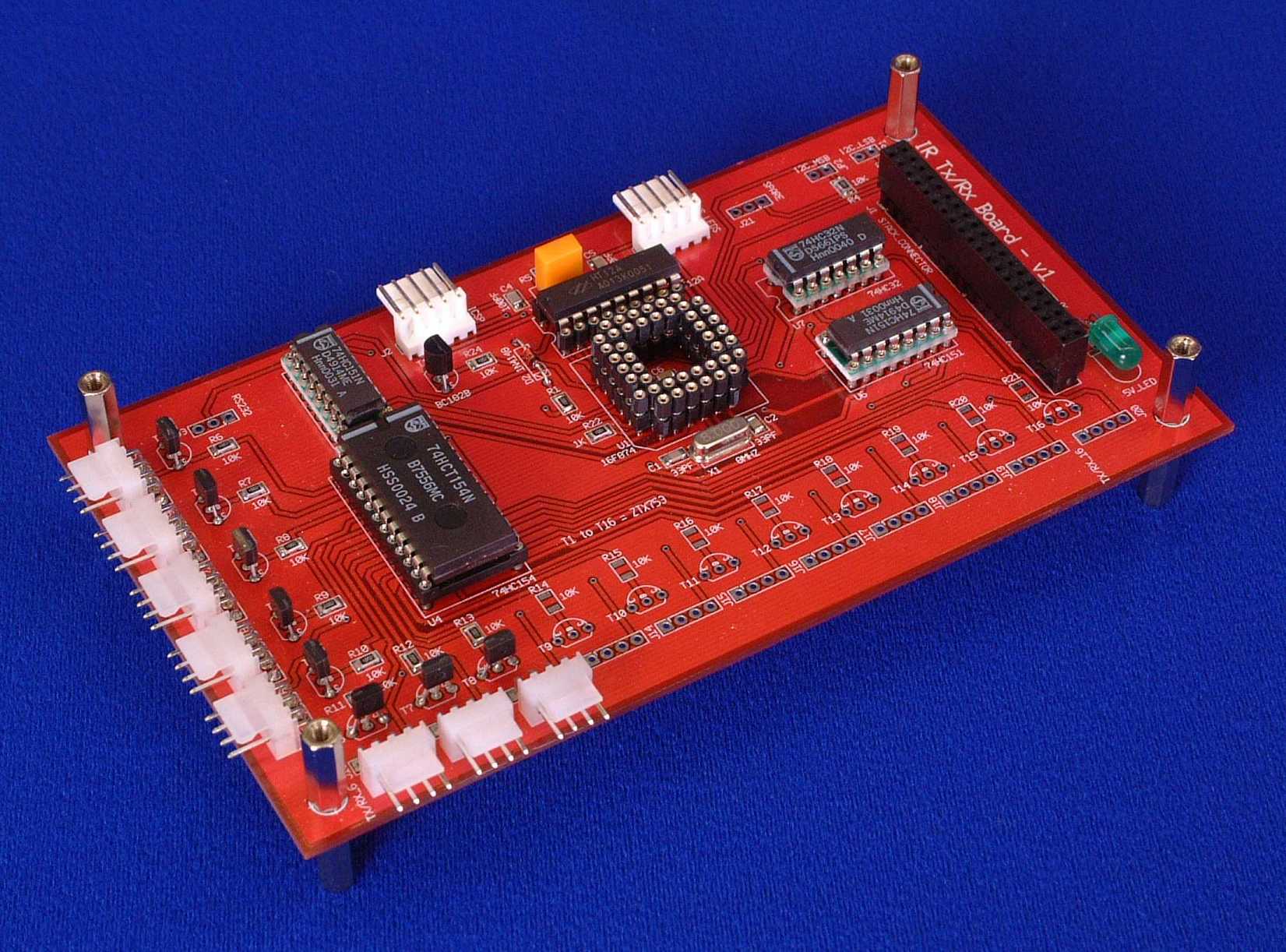
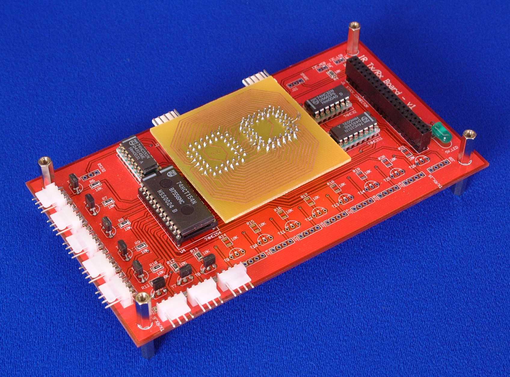
The Infrared Localisation Module uses infrared emitters and receivers to locate either other robots or the base station. Each IR Module can support up to 16 sets of IR Emitters and Receivers, which are placed around the gondola and blimp envelope. This method of communication is very similar to the standard infrared remote controllers used for TVs and Videos around the home. The photo below shows a populated PCB, both with and without adapter module (more about this later).
|
|
|
|
|
The IR Localisation Module (As should have been)
|
The IR Localisation Module with (mistake) Adapter
|
| How it Works
|
|
A circuit diagram for the Infrared Localisation Module in PDF format can be downloaded here, or a GIF version can be viewed here. U1 is a PIC 16F874 microcontroller, chosen because of the number of IO pins required for this circuit (33). Infrared data is generated by U2, a Holtec HT12A, which produces 12 bit serial data modulated onto a 38Khz carrier wave. The microcontroller controls the data transmitted by U2 with connections to A7-A0 and D11 to D8. These bits represent the Blimp ID No. (5 Bits - value 1 to 31), Sensor No. (5 Bits - value 1 to 31), In position indicator (1 Bit - value 0 or 1) and a Spare bit for future use. The microcontroller U1 receives instructions regarding what data should be transmitted via the I2C connection to the Master Control Module. The modulated data from U2 is then passed via an inverting transistor to U4, a 16 way de-multiplexor. Each of the 16 outputs on the de-multiplexor are connected to 1A PNP transistors. These power transistors are used to drive the 16 banks of IR Transmitting LEDs located about the robot. Reception of IR data is handled by Sharp IS1U60 remote control receivers. These are about the size of a power transistor and contain an infrared receiver along with amplification and filtering electronics. When a 38Khz modulated signal is detected, the output of the data out pin changes from high to low. This produces a pulse train that is passed via 2 8-way multiplexors and an Or gate to the Capture input of the microcontroller, where it is decoded. The received data is then stored until the Master Control Module requests it.
|
| What Went Wrong?
|
|
As can be seen in the photographs above, a second small PCB has been added to the module. When I designed the circuits, I drew the schematic with a 40 Pin DIL (Dual In Line) Package for the microcontroller. When I then converted this into a PCB, I changed the package to a surface mount PLCC type, without realising that the PLCC package has 44 pins. The extra 4 pins are not connected but they are dotted around the 4 edges of the chip, starting with pin 1. So pin 1 on my PCB needed to connect to pin 2 on the chip. To correct this mistake I made an adapter that contains a PLCC socket for the microcontroller and 44 pins that plug into the main PCB. By routing the PCB tracks on the adapter very carefully, I was able to produce an fully working fix. The moral of this story, Check, Check and Re-Check the PCB artwork, before sending it away for production. If you have any questions about anything you see on these pages, then please e-mail me at i.mudie@uwe.ac.uk.
|
|