| Master Controller and Radio Communication Module
|
|
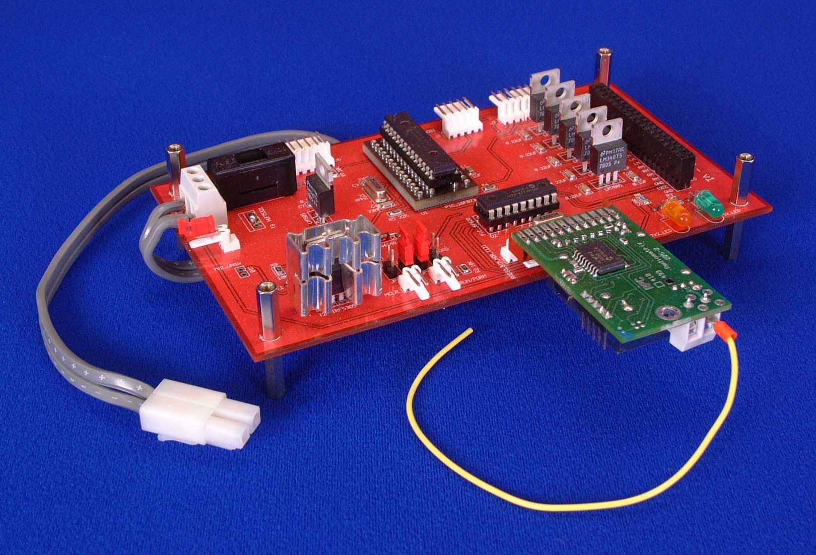
The master control module contains the most powerful microcontroller of any of the modules, a Microchip PIC 16F876 running at 20Mhz. This is because all other modules either feed information to or receive instructions from this module. There is a secondary microcontroller on this module, a PIC 16F628 running at 4Mhz that interfaces the Radiometrix RPC (Radio Packet Controller) Module to the main microcontroller. These devices were connected in this way to enable the main microcontrollers program code to be updated via the radio link (more details of this later). The photo below shows a fully populated PCB.
|
|
A fully populated Master Control PCB with Radio BIM Module
|
How it WorksA circuit diagram for the Master Control Module in PDF format can be downloaded here, or a GIF version can be viewed here. U1 is the main microcontroller. This is connected to U2 (radio interface microcontroller) with five pins. These are Serial RX and TX, Enable Download Signal, Download Complete Signal and Master Clear. To download new program code to the master microcontroller, the following sequence occurs:-
There are jumpers JP1-JP4 that can be used to override the automatic control of the download sequence if required. The PIC can also be programmed via the In Circuit Serial Programming Port (ISCP) by connecting a cable from a PIC programmer to J1. The current battery voltage is monitored by analogue input RA1. This is passed through a potential divider that halves the voltage to bring it below 5 volts (Battery is 7.2 or 8.4 Volts). The power supply for the other modules is produced on this board. Each module is fed from a separate 5v regulator (U4-U8) via the stacking connector J9. The power to these regulator is switched via P-Type FET T2, and is controlled from pin RC0 on U1. This gives the robot a low power mode that is entered when a download is in progress or when the robot is told to sleep. The power to this board is controlled with N-Type FET T3 and an external low current switch connected to J11. The battery voltage passes through a 5A fuse (F1) before anything else just incase a short circuit occurs. If you have any questions about anything you see on these pages, then please e-mail me at i.mudie@uwe.ac.uk.
|
|