uLinux Control Board |
|
The main drawback of using small blimps is the severe weight limitations placed on the design of the electronic control system: the net lift of the inflated envelope is only 200g and approximately half of this (100g) is to be used for batteries. The uLinux control board coupled with the very compact layout and the use of surface-mount technology helps to reduce the weight by a considerable amount.
|
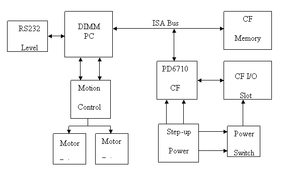
Block diagram of uLinux control board.
|
|
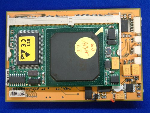
Aerobot Motherboard (uLinux Control Board): The Aerobot Motherboard comprises the following main components:
|
|
uLinux Control Board Top
|
|
DIMM PC Slot: This is a 144 pin SO DIMM connector which is used to interface the DIMM PC to the motherboard. Step-Up Switcher: A step-up DC-DC switching converter and a rechargeable battery supply the 5 volts needed by the electronics. The maximum current consumed by the electronics may exceed 1 Amp, therefore a high current switching converter is needed. The MAX1763 was chosen because it has a load capability greater than 1.5 Amps and is designed to be very low noise (4.7nv/Hz). This converter will work with the input as low as 0.8 volts, maximising the energy that can be drawn from the batteries. However, great care must be taken to ensure the longevity of the Lithium Polymer batteries as these must not be discharged below 2.5v or the cell will be damaged. The battery section covers this in more detail. Motor Control PIC: There is also an 8-bit Arizona Microchip PIC 16F877 microcontroller which runs at a frequency of 14.318MHz giving ample computational power to run the sensors and motors. This microcontroller has 8Kbytes of onboard flash memory, which can be programmed in-circuit via the RS232 serial interface connected to Com1 on the DIMM PC. Serial Port: The motherboard boasts a fully connected RS232 interface which allows connection to a system using hardware flow control. The level converter chip used is a MAX3387E. This interface is connected to Com2 on the DIMM PC.
|
|
Motor Drives: The motor drivers are HIP4020 full bridge drivers and are capable of delivering 500mA in an SO20 surface-mount package. These chips also feature over-temperature and over-current cut-outs to prevent overheating and damage. CF Bridge and Card Slots: In order to allow us to use Compact Flash (CF) I/O and memory cards in the system a host controller interface was required. The interface IC used in this system is a Cirrus PD6710 PCMCIA single slot controller. As the CF standard is very similar to the PCMCIA standard (less address lines) it was relatively straight forward to implement a single CF I/O slot on the motherboard. A second CF slot is available for memory cards only; this slot is connected on the IDE bus and allows memory cards to be seen as slave hard disk drives. Power to the CF slot is controlled by a protected 5/3.3v PCMCIA switching matrix, this allows the use of either 5v or 3.3v CF cards.
|
|
|
|
Home Envelope Gondola Propulsion Controller Ultrasonics Batteries |
|
|