Digital Circuit: Control System
|
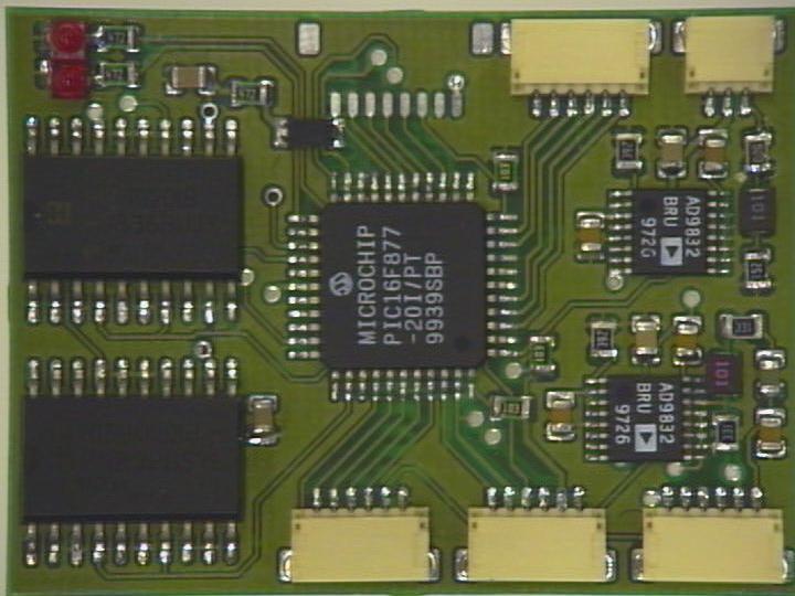
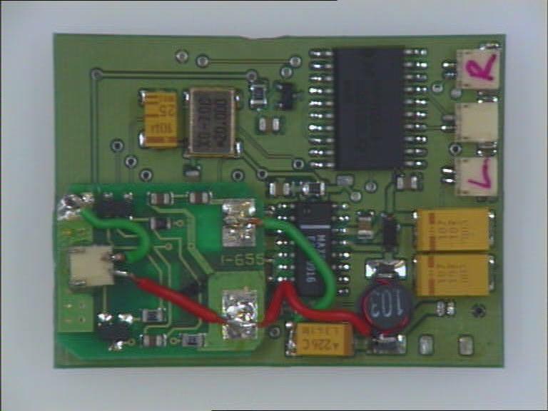
The digital circuit consists of the power generation, motor drives, frequency generators and a microcontroller all of which work at high frequencies producing a lot of noise and therefore, electrical interference. Power Generation: A step-up DC-DC switching converter and a rechargeable battery supply the 5 volts needed by the electronics. The maximum current consumed by the electronics may exceed 1Amp, therefore a high current switching converter is needed. The MAX489 was chosen because it has a load capability greater than an Amp and is designed to be very low noise (4.7nv/Hz). This converter will work with the input as low as 0.8 volts, maximising the energy that can be drawn from the batteries. This device works at a frequency of 300KHz which has some implications for the IR localisation system, which are explained in detail in section 3.6. Motor Control: The motor drivers are HIP4020 full bridge drivers and are capable of delivering 500mA in an SO20 surface-mount package. These chips also feature over-temperature and over-current cut-outs to prevent overheating and damage. The use of this chip helps to keep the component count to a minimum, saving weight and board space over an equivalent circuit built from discrete components. Frequency Generators: The frequency generators used by the transmitter and receiver use direct digital synthesis (DDS) technology to produce near perfect sine waves with minimal external components. The ICs used are AD9832s that are controlled via a three wire serial interface and come in very small (TSSOP) surface mount packages. The original localisation system design by Kelly [1996], used a separate crystal for each frequency, taking up valuable space and adding unnecessary weight. By replacing all the crystals with a single IC, weight, board space and cost were minimised. This new design makes it easier to change and add new frequencies as desired using software. Microcontroller: The heart of the system is an 8-bit Arizona Microchip PIC 16F877 microcontroller, which runs at a frequency of 20MHz giving ample computational power. This microcontroller has 8Kbytes of onboard flash memory, which can be programmed in-circuit via a three-wire serial interface, three 8-bit digital I/O ports as well as an 8 channel 10-Bit AD converter. The unit also features two PWM and three timer modules. The serial port on the PIC can give full RS232 functionality when used in conjunction with a special lead that has a built in level converter chip to provide the correct voltage matching.
|