Analogue Electronics: Localisation System


The Infrared localisation system is based on a design by Kelly [1996] that gives the relative position and distance of the other blimps and allows for low bandwidth inter-blimp communications. There are three types of analogue board that make up the infrared localisation system: the receiver, transmitter and two sensor boards. These boards are fed from a voltage supply that has been filtered to minimise the noise induced by the high speed switching of the digital devices.

Receiver

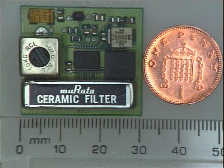
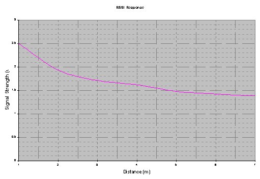
The heart of this system is the receiver which is based on a low power Phillips SA607 FM demodulator IC which has a logarithmic received signal strength indicator (RSSI). This RSSI signal is fed into an analogue to digital converter (ADC) on the control board and is used to calculate the distance to the transmitter being scanned. The graph below shows the RSSI plotted against distance, which demonstrates that for the most part the relationship is logarithmic and can be easily converted to a relatively accurate distance measurement.


SA607 FM Decoder Reciever Board


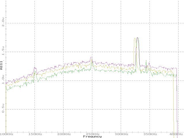
The system uses Frequency Division Multiplexing (FDM) where each blimp transmits on a separate frequency which is selected to minimise interference between the blimps or noise present in the environment. There are a range of sources of noise that could interfere with the infrared system, especially at the frequencies being used (200KHz to 600KHz). One of the main sources of noise within the experimental environment is the high efficiency fluorescent lighting, which tends to operate at approximately 50KHz causing noise at this frequency and the frequency of the harmonics, however, there is not much of this harmonic noise above 200KHz. Therefore the system operates above 200KHz to avoid this noisy part of the frequency spectrum. As was mentioned earlier the on board switching power converter operates at approximately 330KHz causing a huge noise spike around this frequency (see figure 3.12). The number of available useable frequencies is therefore limited by sources of noise and harmonic interaction between each frequency. Therefore, each of the blimp frequencies used was chosen so as to minimise these problems. A frequency scan of the background noise is shown in figure 3.12 below, this frequency plot was produced by importing the RSSI signal from the blimp into a program running on a laptop. The lower part of the frequency spectrum (100 - 200KHz) has a lower noise level because the circuit is tuned for use above 200KHz.


Transmitter

The infrared transmitter consists of a semicircle of 6 LEDs which give 180 degree coverage to the rear of the blimp. The LEDs used are inexpensive high power infrared emitters 'HIRL5015' which have a half power angle of 60 degrees. Each LED is 30 degrees apart in the same plane so that the light from adjacent LEDs overlaps, giving a radiant intensity which stays approximately constant with respect to angle, thus minimising the lobing effect. Two LEDs are placed in series and fed with a 5v sine wave at 100mA, this drive voltage is produced using high output current Op-Amps fed from one of the frequency generators. The use of a sine wave to drive the LEDs instead of a square wave as in Kelly's design gives a very clean output with few harmonics. By using these LEDs in conjunction with the sine wave it is possible to achieve a range in excess of 20m, nearly twice that of Kelly's original design.


As discussed above, each blimp transmits its own unique signal so that it is possible to differentiate between the blimps. Each blimp scans all other frequencies in use except its own, since scanning its own signal would result in a very high RSSI signal due to the close proximity of the transmitter to the receiver.


Sensors

Each blimp is fitted with three forward-facing infrared sensors arranged as a pyramid with its point facing forward to give an approximate hemispherical field of view. Each of the infrared sensors can be selected through an 8-1 analogue multiplexer, with the possibility of adding a further five sensors to expand the system if required. The relative position of any blimp being scanned can be calculated by comparing the data received from each sensor.